CHALLENGE RESULTS ANNOUNCED
20 July 2020
Air Force Research Laboratory, Materials & Manufacturing Directorate Structural Materials, Metals Branch (AFRL/RXCM) and America Makes, proudly announce the additive manufacturing (AM) Modeling Challenge series top performers. See the full [America Makes press release here.]
Challenge 1: Macro-scale Process-to-Structure Predictions Given processing details, predict macroscale residual strain. Top Performer: Dassault Systems Government Solutions Corp
Challenge 2: Micro-scale Process-to-Structure Predictions Given processing details, predict deposit geometry and microstructural details at the single bead, single layer scale Top Performer: The Wing Kam Liu Group, Northwestern University
Challenge 3: Macro-scale Structure-to-Properties Predictions Given representative microstructure characteristics, predict aggregate stress-strain behavior. Top Performer: QuesTek Innovations LLC
Challenge 4: Micro-scale Structure-to-Properties Predictions Given an explicit microstructure representation, predict aggregate stress-strain behavior and strain in particular grains. Top Performer: University of Utah, Carnegie Mellon University and Los Alamos National Lab (Dr. Ashley Spear, Dr. A.D. (Tony) Rollett, Dr. Ricardo Lebensohn)
ACCESSING THE DATA
-
STEP 1: [Create a free Globus account] using institutional credentials, Google ID or ORCID. Globus is required to access the datasets.
-
STEP 2: [Join this Globus Group] to gain access to the Air Force Research Laboratory (AFRL) Additive Manufacturing (AM) Modeling Challenge Series data packages. Joining the group does not obligate you to participate in the challenge, but is required to obtain the data packages.
-
STEP 3: [Subscribe Here] to receive email updates about the AFRL AM Modeling Challenge Series – including information on dataset availability. (Contact information collected here will only be used to send pertinent updates for the challenges.)
CHALLENGE DATA
For each challenge listed below, there are links to the Problem Statement, Dataset, and Answer Template. The Dataset must be accessed through Globus where individual files from the dataset can be transferred to a location of your choice. If the Dataset link below takes you to ‘Error Fetching Search Record’ page, make sure you are signed into Globus AND click the Login link in the upper right hand corner to sign in using your Globus account information.
To access the datasets, click the “Globus” link under the “Get the Data” section, which should redirect you to Globus’ web application. Data may be transferred from Globus to your computer by setting up an endpoint. Documentation on establishing a Globus endpoint for each operating system is found here: MacOs, Linux, Windows. Once an enpoint is established, the Globus web application is used to conduct the download. Information on transferring data from Globus is found here.
CHALLENGE 1: Macro-scale Process-to-Structure Predictions
Given processing details, predict macroscale residual strain.
[Problem Statement] [Dataset] [Answer Template]
CHALLENGE 2: Micro-scale Process-to-Structure Predictions
Given processing details, predict deposit geometry and microstructural details at the single bead, single layer scale.
[Problem Statement] [Dataset] [Answer Template]
CHALLENGE 3: Macro-scale Structure-to-Properties Predictions
Given representative microstructure characteristics, predict aggregate stress-strain behavior.
[Problem Statement] [Dataset] [Answer Template]
CHALLENGE 4: Micro-scale Structure-to-Properties Predictions
Given an explicit microstructure representation, predict aggregate stress-strain behavior and strain in particular grains.
[Problem Statement] [Dataset] [Answer Template]
QUESTIONS & ANSWERS
Answers that AFRL provided to questions about the challenges have been posted here.
GENERAL
What is the preheat temperature of the build plates?
The programmed build plate preheat temperature was set to 80°C for all builds used in the challenge series.
What is the temperature inside the chamber (i.e., above the powder) during the build?
No temperature data inside the build chamber was collected.
What was the laser beam diameter?
We did not directly measure the laser spot size during these experiments/builds. From the manufacturer’s data sheet: Gaussian laser spot diameter (4σ) = 0.1 mm (Challenge 2 Problem Statement slide 13). Note: Challenge 2 builds were fabricated without making adjustments to the laser spot size value, therefore the value is internally consistente whithin the data sets even if it deviates from the manufacturer’s stated nominal value.
What is the atmosphere used to print the challenge samples?
Argon
What is the expected temperature of the deposited powder once leaving the hopper?
This value was not measured. There was no intentional heating of the powder in the hopper.
Is that “brief abstract” mentioned in the Grading section of this page intended to be the same as the “model description” paragraph in the answer template overview slide?
Yes. The language in the grading section has been updated to clarify.
CHALLENGE 1
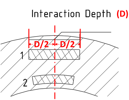
For Challenge 1, are the strain measurements measured tangentially through the thickness (1), or are they measured concentrically (2)? And if it is tangentially measured, would the interaction depth be 2.7mm? And for the tangent measurement, is the process to essentially measure one centered point as it gets near the outside radius?
In this schematic provided by the questioner, the regions labeled 1 and 2 correspond to the two options for the location of the strain measurements noted in the question. The strains are measured tangentially through the thickness (region 1). Yes, the interaction depth for the horizontal component of strain is 2.7mm and the vertical component of strain is 4.6mm. The interaction depth measurement was centered left/right as per this schematic. The measurement grid for the tubes was created by essentially moving up/down and in/out of the page (in the previously linked schematic).
I would like to confirm that we only need to provide strain prediction based on the given coordinates and can safely ignore the non-uniformity of given grid points
Confirmed. Use only the provided coordinates in the Answer Template. We are only asking for predictions in locations where measurements were taken. In some samples measurements were not on a uniform grid. See slide 30, Fig 22 of the Challenge 1 Problem Statement for examples.
According to slide 30 in Challenge 1, for tube samples (A67 - A69), is the measured plane (R’Z’) for residual strains lied parallel to the x-axis of the built plate?
For Z’ = constant, measurements are parallel to the build plate. We do not know the precise (θ’) orientation of the tube challenge articles during EDD measurement, however the principal components of strain that were measured in each tube were the normal components of strain in the radial (R’) and axial (Z’) directions (slide 9).
Correction/Clarification Challenge 1 slide 9:
-
Fig 5 should read : Local coordinate system for tube articles. R’ θ’ Z’ is the polar coordinate system for the tubes where the origin is on the build plate, centered at the center of the tube. θ’=0 X’ - The R in the schematic should be R’
CHALLENGE 2
Is it correct that the 10 layers in the B21.cli represent a multi-layer formation? This would be in contrast to B27.cli which would represent 30 tracks of one layer formation.
Yes, B21 is a single track wall that is 10 layers tall. B27 is a 2D pad composed of multiple tracks with in a single layer. Slides 10 and 21 from the Challenge 2 Problem Statement are good references.
Regarding the multi-layer, thin-wall cases for Challenge 2, what is the dwell time between the deposition of each layer, if any?
Please refer to the HomeIn_Build B.csv file located in the Input data folder in the Challenge 2 data set for the layer times. Refer to the Challenge 2 Problem Statement slide 9 (substrate and timing) for a description of processing to help you interpret the HomeIn file.
Is detailed information (i.e. location, size, deposition path) of the substrate block available?
- Location and size information of the substrate blocks for each sample can be found in the Build B- All Parts.stl file located in the Calibration folder of the Challenge 2 dataset.
- We do not have CLI files for the substrate blocks under the challenge problem.
- Please refer to the Challenge 2 Problem Statement slides 6-9 for general description of scan strategies and substrate blocks (slide 9).
For Challenge 2, what is the difference between “D” and “D_tot”?
The Challenge 2 problem statement document describes a total depth measurement “D_tot”, but the answer template does not contain a matching column, instead it has a column labeled “D”. These quantities are identical, make measurements of D_tot as described in the Challenge 2 problem statement and place them in the column “D” in the answer template. You do not need to change the column header in your answer template, but we will consider any column labled either “D” or “D_tot” to count as an answer for “D_tot” as described in the problem statement.
CHALLENGE 3
Can you provide more precise details on the post-build heat treatments (temperatures and times for SR, HIP, and HT) for Challenge 3 samples?
No specific heat treatment details will be provided. The challenge is to predict aggregate stress-strain behavior given representative microstructure characteristics. Please see the problem statement and dataset for available calibration and input data.
For Challenge 3, what is the strain rate for final measurement?
The milli-tensile specimens were deformed under stroke/displacement control with a target strain rate in the elastic regime of 8.333e-5 mm/mm/sec. This stroke rate value was used for the whole tensile test – from 0 load through yield and through final failure.
CHALLENGE 4
For Challenge 4, on slide 20, it states “hold for measurement”. How long is the holding period during each measurement? During the measurement, is the displacement constant or load?
Hold times varied. The specimen was held at a given state for 2-3 hours for measurement. During these holds the machine remained in load control.
For Challenge 4, it is mentioned that the holding period is about 2-3 hours. It is a long time. Does the authority have any load/displacement vs time history data available for the material?
For the higher stress load states we unloaded the specimen by 50MPa after we reached the target stress level/state to avoid any relaxation/creep within the material during the 2-3 hour hold time. This is standard practice for loading and measuring of HEDM specimens at or near the yield surface.
In the Challenge 4 problem definition, it states that engineering strain was measured with DIC. Can you provide any more details related to this?
The DIC data was a two point correlation, not full-field. Essentially we tracked the distance between two reference points along the gage section and calculated engineering strain as (“new distance” - “original distance”) / “original distance”. Also, the two reference points extended beyond the volume of material used in the challenge, as averaging over a longer distance improves strain sensitivity.
In the Challenge 4 data set, we expect that the Bunge Euler angles φ1, Φ, φ2 should have ranges of [0, 2π], [0, π], [0, 2π], respectively. However, we observe that Φ does not appear to take up this full range. Can you provide any clarification?</br> It is true that the total range of valid Bunge Euler angles are [0, 2π], [0, π], [0, 2π]. However, the provided Euler angles have been reduced to the Rodrigues fundamental zone for cubic crystal symmetries (point group 432). This reduces the maximum range for Φ when the Rodrigues representation is mapped back into Euler space (in Euler space, unlike in Rodrigues space, the fundamental zone for cubic symmetries is disjoint). Please refer to this paper for mathematical details and visualizations of the fundamental zones in both Rodrigues space and Euler space. In particular, Eq. 11 provides the mapping from a Rodrigues vector to Euler angles. Fig. 16 provides a visualization of the fundamental zone for 432 in Euler space; note that the zone does not extend to π for the second Euler angle Φ.
ELIGIBILITY
Challenge problems are open to academia, small and large businesses, national laboratories, both in the U.S. and internationally. Data packages will be publicly released by AFRL and made available to participants. Contact information will be required for accessing data packages to allow for challenge updates to be communicated but does not obligate participation. Submissions will be kept private during grading but will be shared anonymously as an aggregate after grading. Only AFRL will know the identity associated with each submission at any time. If a participant is selected as a Top Performer in one of the challenges, then that participant must agree to openly associate their identity with the submission. Participants will be informed of their submission’s grade/quality and can see other submissions in an anonymous form in a debrief document/journal article. Participants interested in having their submission graded, but not considered for an award, may discuss with AFRL regarding inclusion in the anonymous aggregate. Any questions regarding eligibility to participate or accept Top Performer recognitions should be addressed to AFRL through the challenge participation site. Participants may submit multiple times but must detail the differences in their modeling approach in the form of a brief abstract, as detailed in the grading section below. Participants should limit themselves to a reasonable number of submissions and are subject to AFRL discretion on how many will be reviewed if more are submitted.
TOP PERFORMERS - RECOGNITIONS
Challenge problems will have a plaques and recognitions for all Top Performers. All participants are eligible for Top Performer recognitions.
AWARDS
There is also an associated monetary and/or resource award that may be issued to Top Performers if they meet eligibility requirements and submit the required documentation. Exact details of the breakdown of prize money/resources is under development and award amounts will be communicated through the challenge participation site and may be determined by number of participants. Likely, winners and runners-up of each challenge will receive awards. An independent third-party will coordinate awards with selected Top Performers.
AWARD ELIGIBILITY
To be eligible for the monetary and/or resource award, participants must completely fill in and sign the Air Force Research Laboratory (AFRL) Additive Manufacturing (AM) Modeling Challenge Series Agreement with the National Center for Defense Manufacturing and Machining (NCDMM) who will act as the independent third-party administrator for the awards. Submit your completed agreement to challenge@americamakes.us within a week of challenge submission.
NOTE: Use the DoD Safe SHA-256 Checksum for the ANSWER SUBMISSION CONFIRMATION NUMBER.**
LOGISTICS
Data packages will carry unlimited data rights to the participants with proper citation. Submissions will be the property of the corresponding participant. AFRL is requesting rights to use the submissions in derivative work, but will not distribute submissions directly without approval of the corresponding participants. ARFL will use submissions as an anonymous aggregate unless participants make individual arrangements with AFRL. Participants will be asked to submit results and relevant details of their simulation procedure using a template provided with the challenge problem data package. The simulation details will be treated with the same rights and procedures as the results themselves. It should be noted that AFRL is not setting any constraints on the modeling approaches allowed by participants. Further, any additional information available in literature can be utilized by participants, but should be reported with the submission.
GRADING
Challenges will be graded by awarding points for each requested prediction, based on accuracy. For each requested prediction, levels generally deemed “Excellent” > “Good” > “Acceptable” have been established and points will be awarded in increasing value for obtaining each level. Each challenge problem consists of numerous (> 10) requested predictions. It is not required that any given submission make all requested predictions, but no points will be earned for unmade predictions. Each submission should have a brief abstract accompanying the provided answer template detailing the general modeling methodology used to make the predictions (use the ‘Model Description, Narrative format’ cell in the Overview tab of the answer template). Lack of an abstract and refusal to provide one may result in decremented points. Only answers submitted in the provided answer template (included in the data set) will be graded.
SUBMISSION
The answer templates included in each challenge data set must be used for all submissions. Each answer template includes an overview sheet that must be completely filled in. Answers submitted in any other form will not be graded.
Record the generated submission number for personal records and for the NCDMM award eligibility agreement. To be eligible for award through NCDMM, teams/participants must submit a completed agreement to NCDMM no later than 2 weeks after challenge submissions are due.
SCHEDULE
Schedule updates will be posted here and communicated to all registered participants via email. The deadline to submit challenge answers is January 31, 2020. AFRL will grade submissions and announce Top Performers approximately four (4) months after the submission deadline. A workshop will be hosted to debrief participants on the results and honor the Top Performers.
QUESTIONS
All questions related to the challenge and the data provided should be directed to marie.cox@us.af.mil.
DISCLAIMER
The Air Force Research Laboratory (AFRL) uses its best efforts to deliver a high-quality data and analysis. However, AFRL makes no warranties to that effect, and AFRL shall not be liable for any damage that may result from errors or omissions in the provided data.
The appearance of hyperlinks does not constitute endorsement by the U.S. Air Force of this Web site or the information, products, or services contained therein. For other than authorized activities such as military exchanges and morale, welfare and recreation sites, the U.S. Air Force does not exercise any editorial control over the information you may find at these locations. Such links are provided consistent with the stated purpose of this DoD Web site